Two phase flow heat transfer in nuclear reactors with emphasis to transient phenomena
Introduction
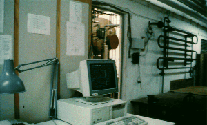
Two phase flow heat transfer in light water cooled nuclear reactors (LWR) is an important area of Nuclear Engineering. The complex phenomena observed during both the steady state and especially the transient operation of a LWR necessitates, besides the theoretical, extensive experimental studies. Theoretical studies of two phase flow phenomena are conducted since 1978 in our Section and numerical computer codes have been developed (Simopoulos 86, Konstantaropoulou & Simopoulos 91).Between 1987-1990 an experimental facility was designed and constructed. Thorough experimental studies of transient heat transfer phenomena with emphasis the rewetting phenomena is being conducted.
The Rewetting Phenomenon
All types of power-producing, water cooled nuclear reactors have coolant circuits which operate at high pressures, ranging from about 70 bar in the boiling -water reactor (BWR) and the steam-generating heavy-water reactor (SGHWR) to 150 bar in the pressurised-water reactor (PWR). Any unexpected decrease in coolant flow through a reactor core leads to serious consequence for the plant as a whole. Such a drop in flow can be caused by anything from a leak in a small pipe to the complete severance of a major coolant pipe wich could lead to a loss-of-coolant accident (LOCA). An emergency core-cooling system (ECCS) should be operated in this case in order to prevent the uncovered fuel elements from melting because of fission product heating. The reestablishment of a cooling liquid film, or the rewetting of the overheated fuel elements is a process of particular importance in the case of such an accident.
Nearly all two-phase flow regimes, pre-dry-out, dry-out and post-dry-out may appear in the course of a rewetting process. Several water experiments have been carried out to simulate the rewetting phenomenon and to predict the liquid cooling film behaviour.
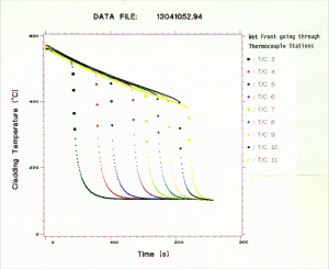
The temperature history of a position on a fuel element before and after the ECCS activation has been experimentally and theoretically investigated. At the beginning, the cooling has very little effect and hence the temperature continues to rise, but with a lower rate, until it reaches a maximum that is called turn round temperature. Then it starts decreasing slowly until a sudden temperature drop occurs. The time at which this rapid temperature fall occurs is known as the quench time. The turn round time, turn round temperature and quench time are important quantities and numerous experiments have been conducted to measure them.
The Experimental Facility
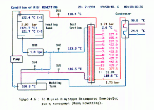
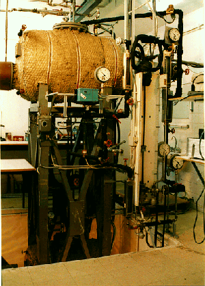
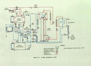
The test facility consists primarily of two fluid loops which supply the test section independently with continuous flow of water and steam as can be seen in the attached diagram
A heating tank fitted with four electric immersion heaters (2x6, 2x12 kW), pressure, temperature and level controlled, is used as a pressurizer and steam generator. Heated liquid at saturation temperature is discharged from the bottom of the heating tank to the test section via a magnetic flowmeter.
Steam leaves the test section to a five branch co-axial double pipe counterflow condenseri and the condensate is accumulated in the holding tank. The pressure in the holding tank is maintained at a pre-set value.
The liquid from the holding tank is pumped into the heating tank by an automatically controlled centrifugal pump. To control the flow of the heating tank, a portion of the discharged liquid can return to the holding tank via a by-pass. The pump discharge line to the holding tank is supplied with a non-return valve.
The desired limits of the liquid levels in the two tanks are maintained with two automatic control level gauge systems, which control the supply of electrical power to the immersion heaters and the pump.
Both tanks are supplied with spring safety relief valves which are provided with discharge connections to outdoors sight glass level gauges and remote level gauges.
The flow to and from the test section can be instantaneously cut-off by the application of solenoid valves.
The main control and safety devices of the rig, as well as other monitor instrumentation, is mounted on a panel.
The Test Section
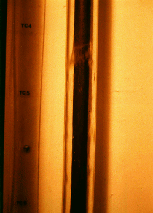
The test section consists of a high pressure and temperature ressistant glass tube with 25.4 mm inside diameter that allows the visual observation of the studied phenomena. The tube encloses a concentric electrically heated rod, inlet supply head and outlet arrangement. During the period from year 1990 to 2000 a glass tube with i.d. 25.4 mm was used, which was then replaced by a glass tube with i.d. 50.0 mm.
The heated rod was manufactured by "Hedin Co. Ltd" as follows: on the outside surface of a stainless steel tube (12.7 mm OD), magnesia powder filled, that accomodates a 4.5 kW heater tape, twelve Iron-Constantan thermocouples were placed at different positions along the tube length. Stainless stell wires were used to keep the thermocouples apart. This structure was inserted in another stainless steel tube (17.4625 mm OD) and then all this assembly was swaged down to 15.875 mm. Thus, the heated rod consists of an indirectly heated stainless steel tube (15.875 mm OD, 3.72 mm thick) which is filled with magnesia powder. Twelve thermocouples are embedded inside the stainless steel sheath and an accurate indication of the wall temperature at different points along the length of the rod is ensured.
The heated part of the rod is 1.016 m and there is a 0.3302 m cold length at each end of the rod. Thermocouples TC1 and TC12 which are positioned in the cold ends of the rod, are used to measure the temperature near the "O" ring seals at the inlet and outlet of the test section. Thermocouple TC11 is connected to a thyristor unit which regulates the power supply necessary to preheat the rod to a given temperature set by a "GULTON" temperature controller. The thermocouple TC11 is connected to a "GOULTON" trip relay system (ON-OFF controller) which will cut-off the power to the test section heater, if the thermocouple accidentally exceds a pre-selected temperature on the controller dial. This is a safety precaution against overheating. Any of the test section thermocouples can be used for experimental observations, provided that it is connected with an appropriate compensating lead to a data acquisition system, as will be discussed later.
The inlet supply head of the test section is designed to supply the heated rod with a uniform falling liquid film, which is discharged through an orifice. Steam is supplied to the test section through a porous disc situated at the side of an annular space between the glass tube and the rod, such that it does not disturb the liquid falling film at its inlet to the test section. The lower end of the glass tube is connected to an arrangement by which steam and liquid can leave the test section separately.
Data Acquisition and Analysis
The whole facility have been supplied with transducers and actuators in order to operate entirely automatic. There are about 50 temperature, pressure, liquid and vapour flowrate, level and bi-stable condition indicators and sensors. Pressure inside the heating tank and at the inlet and outlet of test section is been monitored by 3 pressure transducers. Liquid volume flowrate at the inlet and the outlet of test section is being continuously measured by two very accurate Magnetic Flowmeters. Steam volume flowrate at thw inlet of test section is being continuously mesured using a variable area flowmeter with analog signal output.
The analog signals from the transducers are multiplexed and then led to an analog-to-digital converter directly connected on the bus of an 80386/40MHz PC IBM-compatible.
A FORTRAN program, calling ASSEMBLY routines, user friendly menu-driven, is monitoring the facility and performs data acquisition with rates of up to 100 samples per second.
The data collected are automatically transfered via a Local Area Network to an HP-9000/370 UNIX-Based mini computer where specific fortran programs calling computational and graphical routines display and print suitable diagrams describing the phenomena.
Cladding temperature history and wet-front propagation
A representative diagram of a collected-data processing of a rewetting experiment in atmospheric conditions (1 bar pressure, 550 °C initial wall temperature, 0 K subcooling and without steam flowrate) is been attached. This diagram clearly demonstrates the temperature profile during rewetting of each one of the twelve thermocouples in the rod. A method was also introduced to calculate the wet front position along the rod.
Experiments have been run to investigate the wet front propagation under pressures 1-7 bars for various initial wall temperatures, 0 K subcooling, minimum steam flowrate and liquid flowrate of 1 L/min.
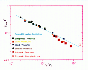
Finally, a simulation correlation proposed in Simopoulos 86 was extrapolated down to 1 bar with data produced from this facility.

![Prometheus [NTUA]](../images/ntua.png)


![[+]](../images/zoom.png)
